The objective of the project is to convert a Porsche 911 Carrera in an electric car with similar or better performance.
Project description
The car
Key Charactristics

Wednesday, March 17, 2010

Mounting the motor and the controller

Motor Install

Big step this week!!! The motor is finally mounted on the frame.
Next step is to put it back on the car. It's starting to be a little heavy to carry alone, so next time we are two I will put it in place and take a couple picts.
The controller is not fixed yet. I need to make sure there is enough space on top.
I am waiting for some spacer from Electro Auto to finish the assembly.

Adaptor Plate Assembly

AdptorPlate Assy

I received the parts from Electro Auto just before Christmas. I had to do some small changes to the adaptor plate because of the flywheel not clearing probably. I machined a small recess of 1/8 just to give more room for the flywheel.
Thanks to Dan from electro Auto, the assembly process was very easy. Heated the spacer ring at 400deg for about 15mins to expand the diameter a little to have slide inside the adaptor plate and the motor plate.
I assembled the bushing on the shaft but I still need to position the flywheel to meet the Magic Distance. It shouldn't be to hard.

Building the Motor mount

Mouter mount 1

This post shows the assembly process of the motor mount.
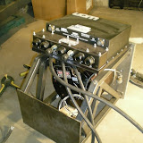
The first step was to weld the 4 nuts on the little flat surfaces. The nut will be hidden inside the tube since the bolt comes from the other side of the adaptor plate. I am impressed how well it worked out. Plenty of cleareance for the bolt on the transmission side.
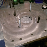
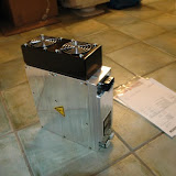
The second step was to locate the rear plate and level the bottom bars.The bars are 1.25" square tubes and 0.086 in thick.
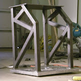
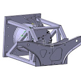
The last step was to triangulate the entire structure the same way as the FEM analysis to take all the loads.
The result is very nice and i'm very happy about it.
Since it's my first week welding I preferred to tac weld all the parts in place but leave the full weld to an experience welder. I wouldn't want a weld to break since all the loads go through these welds.

3D model of the motor Area

Model3D

This is a quick presentation of the 3D model of the rear motor area. You can see the adaptor plate with the frame that will replace the original motor structure.
The part on the rear is an origin part. It has two mounting points on top to hold the motor to the structure of the 911.the last ounting point is on front of the tranismission.
The controller will be on top as shown on the picture. I need to make sure the cooling hoses don't go too high so that the cooling reservoir is the highest point.
You can see 5 batteries packs on the left. The battery racks are not done in 3D because it would take to much time. The same 5 packs will be on the right side and 4 packs will be on front of the car.

FEM Analysis


Thanks to Olivier, we simulated in FEM the way the motor mount would react under the load of the motor. After a couple of modifications to the design to add triangulations everything seems to be good. A little overdesign but it's ok.
The structure is 11Kg, not so bad for a security factor of 10.
Look at the little video to see how the motor reacts under the load. It's cool... (the load on the video simulates 180KW regen)

All part from Metric Mind are in!

Parts From MMC

I haven't posted for a long time but the project is still going well. Ok it's going a little slow, but with work it's hard to spend more than 10-15 hours a week.
A couple posts should follow soon!

Ok so for the parts. We received them just before Chrismas. None are installed yet, but they should start to go in next month.

Vaccum Pump for the breaks: MES-DEA 70/6E2 -Low noise and very small!

Water Heater MES-DEA Water Heater RM4 200-450V 4kW

DC-DC converter: 400-1000 MES-DEA 400-1000


And finally for the Charger: NLG513-Sx BRUSA. 3KW charger. Will charge the pack overnight. If we need to charge faster, I'll add another one in parrallel.