The objective of the project is to convert a Porsche 911 Carrera in an electric car with similar or better performance.
Project description
The car
Key Charactristics

Monday, December 12, 2011

Battery pack update

batteryPack3


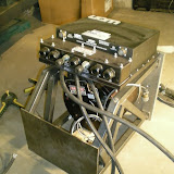
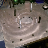
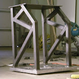
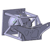
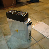
Ok, here is an update on the battery pack.
All the cells are welded as well as the BMS. The packs are ready for finally assembly, and packaging.
I included a couple of pictures to show the progress.

Here is a small description of the pack:
Pack
120 cells in series
Divided into 14 Subpacks

Subpack
Cells: 240 x A123 small ANR26650
Cells configuration: 8 cells in series ( 1 cell = 30 x A123 in parallel (two rows of 15)
Casing: Polycarbonate (White)
Isolator: GP03 Reinforced fiberglass (red)
BMS: 8 Cell Boards (Elithion BMS)


I should post more info after Christmas

Wednesday, March 23, 2011

Battery boxes arrived


Just received the 14 battery boxes. I chose to go with Polycarbonate(Lexan) because it's a plastic that is heat resistant, flame retardant, has high impact strength and high dielectric strength.
Thanks to CasboPlexiglass who made them!

I'll do another post with the details on the battery box assembly!

Motor Installed

Motor Mount 2
(Click on the image above to open album)

Ok, So it's been a while since I posted, but the project was still advancing.
I concentrated mostly on welding the batteries during the winter.
But here is a quick post and pictures on the motor fully assembled.
The motor rack was powder coated for a long durability and to avoid rust.

The assembly of the flywheel with the motor went easily, we tapped in the adapter slowly onto the motor shaft to make sure the magic distance was set perfectly. The magic distance is the distance between the edge of the flywheel to the surface where the motor mounts the transmission. It is very important that this distance is accurate because the pressure plate and the transmission piston is set to this distance.

The actual mounting of the rack onto the car was also no problem since we already checked everything without the electric motor, just a little heavier.

Wednesday, March 17, 2010

Mounting the motor and the controller

Motor Install

Big step this week!!! The motor is finally mounted on the frame.
Next step is to put it back on the car. It's starting to be a little heavy to carry alone, so next time we are two I will put it in place and take a couple picts.
The controller is not fixed yet. I need to make sure there is enough space on top.
I am waiting for some spacer from Electro Auto to finish the assembly.

Adaptor Plate Assembly

AdptorPlate Assy

I received the parts from Electro Auto just before Christmas. I had to do some small changes to the adaptor plate because of the flywheel not clearing probably. I machined a small recess of 1/8 just to give more room for the flywheel.
Thanks to Dan from electro Auto, the assembly process was very easy. Heated the spacer ring at 400deg for about 15mins to expand the diameter a little to have slide inside the adaptor plate and the motor plate.
I assembled the bushing on the shaft but I still need to position the flywheel to meet the Magic Distance. It shouldn't be to hard.

Building the Motor mount

Mouter mount 1

This post shows the assembly process of the motor mount.
The first step was to weld the 4 nuts on the little flat surfaces. The nut will be hidden inside the tube since the bolt comes from the other side of the adaptor plate. I am impressed how well it worked out. Plenty of cleareance for the bolt on the transmission side.
The second step was to locate the rear plate and level the bottom bars.The bars are 1.25" square tubes and 0.086 in thick.
The last step was to triangulate the entire structure the same way as the FEM analysis to take all the loads.
The result is very nice and i'm very happy about it.
Since it's my first week welding I preferred to tac weld all the parts in place but leave the full weld to an experience welder. I wouldn't want a weld to break since all the loads go through these welds.

3D model of the motor Area

Model3D

This is a quick presentation of the 3D model of the rear motor area. You can see the adaptor plate with the frame that will replace the original motor structure.
The part on the rear is an origin part. It has two mounting points on top to hold the motor to the structure of the 911.the last ounting point is on front of the tranismission.
The controller will be on top as shown on the picture. I need to make sure the cooling hoses don't go too high so that the cooling reservoir is the highest point.
You can see 5 batteries packs on the left. The battery racks are not done in 3D because it would take to much time. The same 5 packs will be on the right side and 4 packs will be on front of the car.

FEM Analysis


Thanks to Olivier, we simulated in FEM the way the motor mount would react under the load of the motor. After a couple of modifications to the design to add triangulations everything seems to be good. A little overdesign but it's ok.
The structure is 11Kg, not so bad for a security factor of 10.
Look at the little video to see how the motor reacts under the load. It's cool... (the load on the video simulates 180KW regen)

All part from Metric Mind are in!

Parts From MMC

I haven't posted for a long time but the project is still going well. Ok it's going a little slow, but with work it's hard to spend more than 10-15 hours a week.
A couple posts should follow soon!

Ok so for the parts. We received them just before Chrismas. None are installed yet, but they should start to go in next month.

Vaccum Pump for the breaks: MES-DEA 70/6E2 -Low noise and very small!

Water Heater MES-DEA Water Heater RM4 200-450V 4kW

DC-DC converter: 400-1000 MES-DEA 400-1000


And finally for the Charger: NLG513-Sx BRUSA. 3KW charger. Will charge the pack overnight. If we need to charge faster, I'll add another one in parrallel.

Monday, August 17, 2009

Tabwelder Setup

Tabwedler setup

Ok so we finally got the tab welder to do some constant OK welds. I am not 100% satisfied with the quality, but I give them a 80%... so it's not so bad. Either we stick with this quality or buy a new tab welder. To date this tab welder is far from being the best! We don't have much experience with tab welding, but we seem to have so much problems with it. We can't weld copper, we can't use tungsten rods, it's very hard to do constant welds on thin materials! We have a good setup and we will keep it.

I think the best solution is to do more welds per battery and we will be fine.

Next, I will be reviewing the nickel tab design to include a fuse in between each cell. It's a simple design solution and doesn't cost anything more. The guys that are converting a another Porsche from MIT documented this process. Pretty cool project they have! I also need to check how to machine does tabs... Laser or waterjet??? hmmm.

Quick note on our setup: We made up a rack to hold the welder higher off the ground, like this the battery packs can go underneath the welder. It is easier than making long and complicated extensions from the electrodes holders.

Tuesday, August 4, 2009

Transmission measured, Thanks to WME and SPGdata3D

FARO ARM_Transmission


A couple of weeks ago I started to work on the motor mount and coupling and found that ElectroAuto was making custom adpator plates with a very nice design! After confirming that they could do the custom work for me. It was time to either send the transmission or take the measures myself. However, do to critical alignment of the motor with the transmission, I couldn't get enough accurate measures with a simple caliper.
So I looked and CMM shops and found SPGdata3d and WME near Montreal that could probably help me!
They were so helpful and quick to respond. By Sunday night everything was done! They used a FARO arm to take accurate measures of each mounting holes and the transmission shaft. Take a look at the pictures to see the setup!

Thanks a lot to both Dan Popovici and Jim for the great help, I'll be sure to contact you once the car is done!

Next step! Finalize my design to mount the rear battery rack on the adaptor plate!

Battery Pack Update!

Battery_Pack_update

Quick update on the battery pack!

We received 55 meters of nickel from our Chinese supplier! Very fast delivery! Its 101mm wide and .254mm thick(.010")

We received 300 A123 Batteries and the RIM1000 IR tester to test the internal resistance to make sure they are OK! To date all are good but I only tested 20.

We simulated the packs with some pressed wood to see how well they would fit in the car. It still needs some fine tuning, but it looks for now! It was long to find a good setup to fit those 3420 cells. The pack is devided in 14 sub pack each have 30 cells in parallel and 8 in series to make 24V packs. 10 packs will go in the back and 4 in the front!

I will post more info on the battery pack as we go along.
The next step is to validate that the batteries are all good to go as they are not new. But should be within 98% of there initial capacity. Only time will tell!